Cummins Fault Code 731
Overview
Fault Code: 731
PID: S64
SPN: 723
FMI: 7/7
LAMP: Amber
SRT:
Engine position signal from the crankshaft position sensor and camshaft position sensor do not match.
Possible reduced engine performance.
Circuit Description
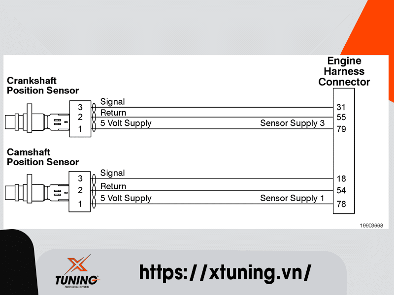
The crankshaft position and camshaft position sensors are Hall effect type sensors. The engine control module (ECM) provides a 5 volt supply to the position sensor and a return circuit. As the teeth on the crankshaft speed ring or the dimples in the back of the camshaft gear move past the position sensor, a signal is generated on the position sensor signal circuit. The ECM interprets this signal and converts it to an engine speed. A missing tooth on the crankshaft gear is used by the ECM to determine the position of the engine.
Component Location
The crankshaft position and camshaft position sensor location varies, depending on engine model.
Conditions for Running the Diagnostics
This diagnostic runs continuously when the engine is running.
Conditions for Setting the Fault Codes
The Engine Control Module (ECM) detected the crankshaft position does not match the camshaft position signal input to the ECM.
Action Taken When the Fault Code is Active
- The ECM illuminates the amber CHECK ENGINE lamp and/or the malfunction indicator lamp (MIL) immediately when the diagnostic runs and fails.
- Diesel exhaust fluid injection into the aftertreatment system is disabled.
Active and stationary regeneration of the diesel particulate filter will be disabled.
Exhaust gas recirculation (EGR) valve operation will be disabled.
Engine torque will be reduced if the engine is operated for an extended period of time with this fault active.
Conditions for Clearing the Fault Code
- To validate the repair using a Diagnostic Road Test, utilize a route that incorporates both stop and go city type driving and steady state highway type driving. It may be necessary to load the unit for certain diagnostics in the ECM to run.
- To validate the repair using a Chassis Dynamometer, utilize a routine that incorporates acceleration and motoring events, steady state highway type operation, and load. This will simulate normal driving and allow the diagnostics in the ECM to run.
- The fault code status displayed by the recommended Cummins electronic service tool or equivalent will change to INACTIVE immediately after the diagnostic runs and passes.
- The ECM will turn off the amber CHECK ENGINE lamp immediately after the diagnostic runs and passes.
- For On-Board Diagnostics (OBD) engines, the ECM will extinguish the Malfunction Indicator Lamp (MIL) after three consecutive trips where the diagnostic runs and passes.
- The “Reset All Faults” command in the recommended Cummins electronic service tool or equivalent can be used to clear active and inactive faults, as well as extinguish the MIL for OBD applications.
Shop Talk
The ECM monitors the position of the missing tooth on the crankshaft speed sensor target and the camshaft speed sensor target. If the two positions do not match, the ECM then determines that there is a mechanical misalignment between the two sensors.
Possible causes of this fault code include:
Engine speed sensor rings that are loose or not aligned correctly
Mechanical misalignment.


